Timer and Counter Instructions
Timers and counters control operations based on time or the number of events.
 Available Instructions
The time base is 1 msec for all timers. For example, a 2 second timer’s .PRE value should be 2000.
Timer On Delay (TON)
The TON instruction is a non-retentive timer that accumulates time when the instruction is enabled (rung-condition-in is true).
Available Languages
- Ladder Diagram

- Function Block
This instruction is available in function block as TONR.
- Structured Text
This instruction is available in structured text as TONR.
Operands
TIMER Structure
Example

Timer Off Delay (TOF)
The TOF instruction is a non-retentive timer that accumulates time when the instruction is enabled (rung-condition-in is false).
Available Languages
- Ladder Diagram

- Function Block
This instruction is available in function block as TOFR.
- Structured Text
This instruction is available in structured text as TOFR.
Operands
TIMER Structure
Example

When limit_switch_2 is cleared, light_2 is on for 180 msec (timer_2 is timing). When timer_2.acc reaches 180, light_2 goes off and light_3 goes on. Light_3 remains on until the TOF instruction is enabled. If limit_switch_2 is set while timer_2 is timing, light_2 goes off.
Retentive Timer On (RTO)
The RTO instruction is a retentive timer that accumulates time when the instruction is enabled.
Available Languages
- Ladder Diagram

- Function Block
This instruction is available in function block as RTOR.
- Structured Text
This instruction is available in structured text as RTOR.
Operands
TIMER Structure
Example

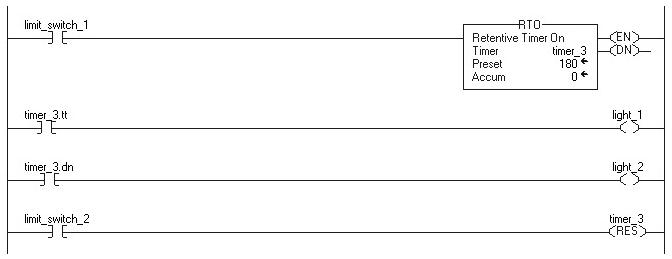
When limit_switch_1 is set, light_1 is on for 180 msec (timer_2 is timing). When timer_3.acc reaches 180, light_1 goes off and light_2 goes on. Light_2 remains until timer_3 is reset. If limit_switch_2 is cleared while timer_3 is timing, light_1 remains on. When limit_switch_2 is set, the RES instruction resets timer_3 (clears status bits and .ACC value).
Count Up (CTU)
The CTU instruction counts upward.
Available Languages
- Ladder Diagram

- Function Block
This instruction is available in function block as CTUD.
- Structured Text
This instruction is available in structured text as CTUD.
Operands
COUNTER Structure
Example

After limit_switch_1 goes from disabled to enabled 10 times, the .DN bit is set and light_1 turns on. If limit_switch_1 continues to go from disabled to enabled, counter_1 continues to increment its count and the .DN bit remains set. When limit_switch_2 is enabled, the RES instruction resets counter_1 (clears the status bits and the .ACC value) and light_1 turns off.
Count Down (CTD)
The CTD instruction counts downward.
Available Languages
- Ladder Diagram

- Function Block
This instruction is available in function block as CTUD.
- Structured Text
This instruction is available in structured text as CTUD.
Operands
COUNTER Structure
Example

A conveyor brings parts into a buffer zone. Each time a part enters, limit_switch_1 is enabled and counter_1 increments by 1. Each time a part leaves, limit_switch_2 is enabled and counter_1 decrements by 1. If there are 100 parts in the buffer zone (counter_1.dn is set), conveyor_a turns on and stops the conveyor from bringing in any more parts until the buffer has room for more parts.
Reset (RES)
The RES instruction resets a TIMER, COUNTER, or CONTROL structure.
Available Languages
- Ladder Diagram

- Function Block
This instruction is not available in function block.
- Structured Text
This instruction is not available in structured text.
Operands
Example
Timer On Delay with Reset (TONR)
The TONR instruction is a non-retentive timer that accumulates time when TimerEnable is set.
Available Languages
- Ladder Diagram
This instruction is available in ladder diagram as two separate instructions: TON and RES.
- Function Block

- Structured Text
TONR(TONR_tag);
Operands
FBD_TIMER Structure
Example
Each scan that limit_switch1 is set, the TONR instruction increments the ACC value by elapsed time until the ACC value reaches the PRE value. When ACC ³ PRE, the DN parameter is set, and timer_state is set.
- Function Block

- Structured Text
TONR_01.Preset := 500;
TONR_O1.Reset := reset;
TONR_01.TimerEnable := limit_switch1;
TONR(TONR_01)
timer_state := TONR_01.DN;
Timer Off Delay with Reset (TOFR)
The TOFR instruction is a non-retentive timer that accumulates time when TimerEnable is cleared.
Available Languages
- Ladder Diagram
This instruction is available in ladder diagram as two separate instructions: TOF and RES.
- Function Block

- Structured Text
TOFR(TOFR_tag)
Operands
FBD_TIMER Structure
Example
Each scan after limit_switch1 is cleared, the TOFR instruction increments the ACC value by elapsed time until the ACC value reaches the PRE value. When ACC ³ PRE, the DN parameter is cleared, and timer_state2 is set.
- Function Block

- Structured Text
TOFR_01.Preset := 500;
TOFR_01.Reset := reset;
TOFR_01.TimerEnable := limit_switch1;
TOFR(TOFR_01);
timer_state2 := TOFR_01.DN
Retentive Timer On with Reset (RTOR)
The RTOR instruction is a retentive timer that accumulates time when TimerEnable is set.
Available Languages
- Ladder Diagram
This instruction is available in ladder diagram as two separate instructions: RTO and RES.
- Function Block

- Structured Text
RTOR(RTOR_tag)
Operands
FBD_TIMER Structure
Example
Each scan that limit_switch1 is set, the RTOR instruction increments the ACC value by elapsed time until the ACC value reaches the PRE value. When ACC ³ PRE, the DN parameter is set, and timer_state3 is set.
- Function Block

- Structured Text
RTOR_01.Preset :=500;
RTOR_01.Reset := reset;
RTOR_01.TimerEnable := limit_switch1;
RTOR(RTOR_01);
timer_state3 := RTOR_01.DN;
Count Up/Down (CTUD)
The CTUD instruction counts up by one when CUEnable transitions from clear to set. The instruction counts down by one when CDEnable transitions from clear to set.
Available Languages
- Ladder Diagram
This instruction is available in ladder as CTU, CTD, and RES.
- Function Block

- Structured Text
CTUD(CTUD_tag)
Operands
FBD_COUNTER Structure
Example
When limit_switch1 goes from cleared to set, CUEnable is set for one scan and the CTUD instruction increments the ACC value by 1. When ACC ³ PRE, the DN parameter is set, which enables the function block instruction following the CTUD instruction.
- Function Block

- Structured Text
CTUD_01.Preset := 500;
CTUD_01.Reset := Restart;
CTUD_01.CUEnable := limit_switch1;
CTUD(CTUD_01);
counter_state := CTUD_01.DN;
- Download to PDF
If you want to:
|
Use this instruction:
|
time how long a timer is enabled
|
TON
|
time how long a timer is disabled
|
TOF
|
accumulate time
|
RTO
|
time how long a timer is enabled with built-in reset in function block
|
TONR
|
time how long a timer is disabled with built-in reset in function block
|
TOFR
|
accumulate time with built-in reset in function block
|
RTOR
|
count up
|
CTU
|
count down
|
CTD
|
count up and count down in function block
|
CTUD
|
reset a timer or counter
|
RES
|
The time base is 1 msec for all timers. For example, a 2 second timer’s .PRE value should be 2000.
Timer On Delay (TON)
The TON instruction is a non-retentive timer that accumulates time when the instruction is enabled (rung-condition-in is true).
Available Languages
- Ladder Diagram
- Function Block
This instruction is available in function block as TONR.
- Structured Text
This instruction is available in structured text as TONR.
Operands
Operand
|
Type
|
Format
|
Description
|
Timer
|
TIMER
|
tag
|
timer structure
|
Preset
|
DINT
|
immediate
|
how long to delay (accumulate time)
|
Accum
|
DINT
|
immediate
|
total msec the timer has counted initial value is typically 0
|
TIMER Structure
Mnemonic
|
Data Type
|
Description
|
.EN
|
BOOL
|
The enable bit indicates the TON instruction is enabled.
|
.TT
|
BOOL
|
The timing bit indicates that a timing operation is in process.
|
.DN
|
BOOL
|
The done bit indicates that .ACC ³ .PRE.
|
.PRE
|
DINT
|
The preset value specifies the value (1 msec units) which the accumulated value must reach before the instruction sets the .DN bit.
|
.ACC
|
DINT
|
The accumulated value specifies the number of milliseconds that have elapsed since the TON instruction was enabled.
|
Example
Timer Off Delay (TOF)
The TOF instruction is a non-retentive timer that accumulates time when the instruction is enabled (rung-condition-in is false).
Available Languages
- Ladder Diagram
- Function Block
This instruction is available in function block as TOFR.
- Structured Text
This instruction is available in structured text as TOFR.
Operands
Operand
|
Type
|
Format
|
Description
|
Timer
|
TIMER
|
tag
|
timer structure
|
Preset
|
DINT
|
immediate
|
how long to delay (accumulate time)
|
Accum
|
DINT
|
immediate
|
total msec the timer has counted initial value is typically 0
|
TIMER Structure
Mnemonic
|
Data Type
|
Description
|
.EN
|
BOOL
|
The enable bit indicates the TOF instruction is enabled.
|
.TT
|
BOOL
|
The timing bit indicates that a timing operation is in process.
|
.DN
|
BOOL
|
The done bit indicates that .ACC .PRE.
|
.PRE
|
DINT
|
The preset value specifies the value (1 msec units) which the accumulated value must reach before the instruction clears the .DN bit.
|
.ACC
|
DINT
|
The accumulated value specifies the number of milliseconds that have elapsed since the TOF instruction was enabled.
|
Example

When limit_switch_2 is cleared, light_2 is on for 180 msec (timer_2 is timing). When timer_2.acc reaches 180, light_2 goes off and light_3 goes on. Light_3 remains on until the TOF instruction is enabled. If limit_switch_2 is set while timer_2 is timing, light_2 goes off.
Retentive Timer On (RTO)
The RTO instruction is a retentive timer that accumulates time when the instruction is enabled.
Available Languages
- Ladder Diagram
- Function Block
This instruction is available in function block as RTOR.
- Structured Text
This instruction is available in structured text as RTOR.
Operands
Operand
|
Type
|
Format
|
Description
|
Timer
|
TIMER
|
tag
|
timer structure
|
Preset
|
DINT
|
immediate
|
how long to delay (accumulate time)
|
Accum
|
DINT
|
immediate
|
total msec the timer has counted initial value is typically 0
|
TIMER Structure
Mnemonic
|
Data Type
|
Description
|
.EN
|
BOOL
|
The enable bit indicates the RTO instruction is enabled.
|
.TT
|
BOOL
|
The timing bit indicates that a timing operation is in process.
|
.DN
|
BOOL
|
The done bit indicates that .ACC .PRE.
|
.PRE
|
DINT
|
The preset value specifies the value (1 msec units) which the accumulated value must reach before the instruction clears the .DN bit.
|
.ACC
|
DINT
|
The accumulated value specifies the number of milliseconds that have elapsed since the RTO instruction was enabled.
|
Example
When limit_switch_1 is set, light_1 is on for 180 msec (timer_2 is timing). When timer_3.acc reaches 180, light_1 goes off and light_2 goes on. Light_2 remains until timer_3 is reset. If limit_switch_2 is cleared while timer_3 is timing, light_1 remains on. When limit_switch_2 is set, the RES instruction resets timer_3 (clears status bits and .ACC value).
Count Up (CTU)
The CTU instruction counts upward.
Available Languages
- Ladder Diagram
- Function Block
This instruction is available in function block as CTUD.
- Structured Text
This instruction is available in structured text as CTUD.
Operands
Operand
|
Type
|
Format
|
Description
|
Counter
|
COUNTER
|
tag
|
counter structure
|
Preset
|
DINT
|
immediate
|
how high to count
|
Accum
|
DINT
|
immediate
|
number of times the counter has counted initial value is typically 0
|
COUNTER Structure
Mnemonic
|
Data Type
|
Description
|
.CU
|
BOOL
|
The count up enable bit indicates the CTU instruction is enabled.
|
.DN
|
BOOL
|
The done bit indicates that .ACC .PRE.
|
.OV
|
BOOL
|
The overflow bit indicates the counter exceeded the upper limit of 2,147,483,647. The counter then rolls over to -2,147,483,648 and begins counting up again.
|
.UN
|
BOOL
|
The underflow bit indicates that the counter exceeded the lower limit of -2,147,483,647. The counter then rolls over to 2,147,483,647 and begins counting down again.
|
.PRE
|
DINT
|
The preset value specifies the value which the accumulated value must reach before the instruction sets the .DN bit.
|
.ACC
|
DINT
|
The accumulated value specifies the number of transitions the instruction has counted.
|
Example

After limit_switch_1 goes from disabled to enabled 10 times, the .DN bit is set and light_1 turns on. If limit_switch_1 continues to go from disabled to enabled, counter_1 continues to increment its count and the .DN bit remains set. When limit_switch_2 is enabled, the RES instruction resets counter_1 (clears the status bits and the .ACC value) and light_1 turns off.
Count Down (CTD)
The CTD instruction counts downward.
Available Languages
- Ladder Diagram
- Function Block
This instruction is available in function block as CTUD.
- Structured Text
This instruction is available in structured text as CTUD.
Operands
Operand
|
Type
|
Format
|
Description
|
Counter
|
COUNTER
|
tag
|
counter structure
|
Preset
|
DINT
|
immediate
|
how low to count
|
Accum
|
DINT
|
immediate
|
number of times the counter has counted initial value is typically 0
|
COUNTER Structure
Mnemonic
|
Data Type
|
Description
|
.CU
|
BOOL
|
The count down enable bit indicates the CTU instruction is enabled.
|
.DN
|
BOOL
|
The done bit indicates that .ACC .PRE.
|
.OV
|
BOOL
|
The overflow bit indicates the counter exceeded the upper limit of 2,147,483,647. The counter then rolls over to -2,147,483,648 and begins counting up again.
|
.UN
|
BOOL
|
The underflow bit indicates that the counter exceeded the lower limit of -2,147,483,647. The counter then rolls over to 2,147,483,647 and begins counting down again.
|
.PRE
|
DINT
|
The preset value specifies the value which the accumulated value must reach before the instruction sets the .DN bit.
|
.ACC
|
DINT
|
The accumulated value specifies the number of transitions the instruction has counted.
|
Example

A conveyor brings parts into a buffer zone. Each time a part enters, limit_switch_1 is enabled and counter_1 increments by 1. Each time a part leaves, limit_switch_2 is enabled and counter_1 decrements by 1. If there are 100 parts in the buffer zone (counter_1.dn is set), conveyor_a turns on and stops the conveyor from bringing in any more parts until the buffer has room for more parts.
Reset (RES)
The RES instruction resets a TIMER, COUNTER, or CONTROL structure.
Available Languages
- Ladder Diagram
- Function Block
This instruction is not available in function block.
- Structured Text
This instruction is not available in structured text.
Operands
Operand
|
Type
|
Format
|
Description
|
structure
|
TIMER
CONTROL COUNTER |
tag
|
structure to reset
|
Example
| Example | Description |
 | When enabled, reset timer_3. |
 | When enabled, reset counter_1. |
 | When enabled, reset control_1. |
Timer On Delay with Reset (TONR)
The TONR instruction is a non-retentive timer that accumulates time when TimerEnable is set.
Available Languages
- Ladder Diagram
This instruction is available in ladder diagram as two separate instructions: TON and RES.
- Function Block
- Structured Text
TONR(TONR_tag);
Operands
Operand
|
Type
|
Format
|
Description
|
TONR tag
|
FBD_TIMER
|
structure
|
TONR structure
|
FBD_TIMER Structure
Input Parameter
|
Data Type
|
Description
|
EnableIn
|
BOOL
|
Function Block:
If cleared, the instruction does not execute and outputs are not updated. If set, the instruction executes.
Default is set.
Structured Text:
No effect. The instruction executes.
|
TimerEnable
|
BOOL
|
If set, this enables the timer to run and accumulate time.
Default is cleared.
|
PRE
|
DINT
|
Timer preset value. This is the value in 1 msec units that ACC must reach before timing is finished. If invalid, the instruction sets the appropriate bit in Status and the timer does not execute.
Valid = 0 to maximum positive integer
|
Reset
|
BOOL
|
Request to reset the timer. When set, the timer resets.
Default is cleared.
|
Output Parameter
|
Data Type
|
Description
|
EnableOut
|
BOOL
|
The instruction produced a valid result.
|
ACC
|
DINT
|
Accumulated time in milliseconds.
|
EN
|
BOOL
|
Timer enabled output. Indicates the timer instruction is enabled.
|
TT
|
BOOL
|
Timer timing output. When set, a timing operation is in progress.
|
DN
|
BOOL
|
Timing done output. Indicates when accumulated time is greater than or equal to preset.
|
Status
|
DINT
|
Status of the function block.
|
InstructFault (Status.0)
|
BOOL
|
The instruction detected one of the following execution errors. This is not a minor or major controller error. Check the remaining status bits to determine what occurred.
|
PresetInv (Status.1)
|
BOOL
|
The preset value is invalid.
|
Example
Each scan that limit_switch1 is set, the TONR instruction increments the ACC value by elapsed time until the ACC value reaches the PRE value. When ACC ³ PRE, the DN parameter is set, and timer_state is set.
- Function Block
- Structured Text
TONR_01.Preset := 500;
TONR_O1.Reset := reset;
TONR_01.TimerEnable := limit_switch1;
TONR(TONR_01)
timer_state := TONR_01.DN;
Timer Off Delay with Reset (TOFR)
The TOFR instruction is a non-retentive timer that accumulates time when TimerEnable is cleared.
Available Languages
- Ladder Diagram
This instruction is available in ladder diagram as two separate instructions: TOF and RES.
- Function Block
- Structured Text
TOFR(TOFR_tag)
Operands
Operand
|
Type
|
Format
|
Description
|
TOFR tag
|
FBD_TIMER
|
structure
|
TOFR structure
|
FBD_TIMER Structure
Input Parameter
|
Data Type
|
Description
|
EnableIn
|
BOOL
|
Function Block:
If cleared, the instruction does not execute and outputs are not updated. If set, the instruction executes.
Default is set.
Structured Text:
No effect. The instruction executes.
|
TimerEnable
|
BOOL
|
If set, this enables the timer to run and accumulate time.
Default is cleared.
|
PRE
|
DINT
|
Timer preset value. This is the value in 1 msec units that ACC must reach before timing is finished. If invalid, the instruction sets the appropriate bit in Status and the timer does not execute.
Valid = 0 to maximum positive integer
|
Reset
|
BOOL
|
Request to reset the timer. When set, the timer resets.
Default is cleared.
|
Output Parameter
|
Data Type
|
Description
|
EnableOut
|
BOOL
|
The instruction produced a valid result.
|
ACC
|
DINT
|
Accumulated time in milliseconds.
|
EN
|
BOOL
|
Timer enabled output. Indicates the timer instruction is enabled.
|
TT
|
BOOL
|
Timer timing output. When set, a timing operation is in progress.
|
DN
|
BOOL
|
Timing done output. Indicates when accumulated time is greater than or equal to preset.
|
Status
|
DINT
|
Status of the function block.
|
InstructFault (Status.0)
|
BOOL
|
The instruction detected one of the following execution errors. This is not a minor or major controller error. Check the remaining status bits to determine what occurred.
|
PresetInv (Status.1)
|
BOOL
|
The preset value is invalid.
|
Example
Each scan after limit_switch1 is cleared, the TOFR instruction increments the ACC value by elapsed time until the ACC value reaches the PRE value. When ACC ³ PRE, the DN parameter is cleared, and timer_state2 is set.
- Function Block
- Structured Text
TOFR_01.Preset := 500;
TOFR_01.Reset := reset;
TOFR_01.TimerEnable := limit_switch1;
TOFR(TOFR_01);
timer_state2 := TOFR_01.DN
Retentive Timer On with Reset (RTOR)
The RTOR instruction is a retentive timer that accumulates time when TimerEnable is set.
Available Languages
- Ladder Diagram
This instruction is available in ladder diagram as two separate instructions: RTO and RES.
- Function Block
- Structured Text
RTOR(RTOR_tag)
Operands
Operand
|
Type
|
Format
|
Description
|
RTOR tag
|
FBD_TIMER
|
structure
|
RTOR structure
|
FBD_TIMER Structure
Input Parameter
|
Data Type
|
Description
|
EnableIn
|
BOOL
|
Function Block:
If cleared, the instruction does not execute and outputs are not updated. If set, the instruction executes.
Default is set.
Structured Text:
No effect. The instruction executes.
|
TimerEnable
|
BOOL
|
If set, this enables the timer to run and accumulate time.
Default is cleared.
|
PRE
|
DINT
|
Timer preset value. This is the value in 1 msec units that ACC must reach before timing is finished. If invalid, the instruction sets the appropriate bit in Status and the timer does not execute.
Valid = 0 to maximum positive integer
|
Reset
|
BOOL
|
Request to reset the timer. When set, the timer resets.
Default is cleared.
|
Output Parameter
|
Data Type
|
Description
|
EnableOut
|
BOOL
|
The instruction produced a valid result.
|
ACC
|
DINT
|
Accumulated time in milliseconds.
|
EN
|
BOOL
|
Timer enabled output. Indicates the timer instruction is enabled.
|
TT
|
BOOL
|
Timer timing output. When set, a timing operation is in progress.
|
DN
|
BOOL
|
Timing done output. Indicates when accumulated time is greater than or equal to preset.
|
Status
|
DINT
|
Status of the function block.
|
InstructFault (Status.0)
|
BOOL
|
The instruction detected one of the following execution errors. This is not a minor or major controller error. Check the remaining status bits to determine what occurred.
|
PresetInv (Status.1)
|
BOOL
|
The preset value is invalid.
|
Example
Each scan that limit_switch1 is set, the RTOR instruction increments the ACC value by elapsed time until the ACC value reaches the PRE value. When ACC ³ PRE, the DN parameter is set, and timer_state3 is set.
- Function Block
- Structured Text
RTOR_01.Preset :=500;
RTOR_01.Reset := reset;
RTOR_01.TimerEnable := limit_switch1;
RTOR(RTOR_01);
timer_state3 := RTOR_01.DN;
Count Up/Down (CTUD)
The CTUD instruction counts up by one when CUEnable transitions from clear to set. The instruction counts down by one when CDEnable transitions from clear to set.
Available Languages
- Ladder Diagram
This instruction is available in ladder as CTU, CTD, and RES.
- Function Block
- Structured Text
CTUD(CTUD_tag)
Operands
Operand
|
Type
|
Format
|
Description
|
CTUD tag
|
FBD_COUNTER
|
structure
|
CTUD structure
|
FBD_COUNTER Structure
Input Parameter
|
Data Type
|
Description
|
EnableIn
|
BOOL
|
Function Block:
If cleared, the instruction does not execute and outputs are not updated. If set, the instruction executes.
Default is set.
Structured Text:
No effect. The instruction executes.
|
CUEnable
|
BOOL
|
Enable up count. When input toggles from clear to set, accumulator counts up by one.
Default is cleared
|
CDEnable
|
BOOL
|
Enable down count. When input toggles from clear to set, accumulator counts down by one.
Default is cleared
|
PRE
|
DINT
|
Counter preset value. This is the value the accumulated value must reach before DN is set.
Valid = any integer
Default is 0
|
Reset
|
BOOL
|
Request to reset the timer. When set, the counter resets.
Default is cleared
|
Output Parameter
|
Data Type
|
Description
|
EnableOut
|
BOOL
|
The instruction produced a valid result.
|
ACC
|
DINT
|
Accumulated value.
|
CU
|
BOOL
|
Count up enabled.
|
CD
|
BOOL
|
Count down enabled.
|
DN
|
BOOL
|
Counting done. Set when accumulated value is greater than or equal to preset.
|
OV
|
BOOL
|
Counter overflow. Indicates the counter exceeded the upper limit of 2,147,483,647. The counter then rolls over to -2,147,483,648 and begins counting down again.
|
UN
|
BOOL
|
Counter underflow. Indicates the counter exceeded the lower limit of -2,147,483,648. The counter then rolls over to 2,147,483,647 and begins counting down again.
|
Example
When limit_switch1 goes from cleared to set, CUEnable is set for one scan and the CTUD instruction increments the ACC value by 1. When ACC ³ PRE, the DN parameter is set, which enables the function block instruction following the CTUD instruction.
- Function Block
- Structured Text
CTUD_01.Preset := 500;
CTUD_01.Reset := Restart;
CTUD_01.CUEnable := limit_switch1;
CTUD(CTUD_01);
counter_state := CTUD_01.DN;
- Download to PDF
 |
0 comments :